Optics and Ray diagrams
Posted: 20 November 2020Optics – like many scientific terms the word has been co-opted in to many other uses. Most prominent at the moment in common usage must be as a political term. Ben Zimmer did some interesting work in uncovering the history as the On Language columnist at the Sunday New York Times Magazine. The first record appears to be from Jimmy Carter’s “inflation counselor,” Robert Strauss, who noted in 1978 that the president’s actions “…would be a nice optical step,” meaning of course that it would look good from a public relations standpoint. Through the 1980’s the word gained traction in the US and then the UK media, probably through French and French-Canadian influence. “Optique.” in addition to all the standard uses in physics, photography, etc is used to mean “perspective” or “point of view”.
Focussing on the physics (if you’ll allow me the pun) – “optics” is the branch of physics that studies the behaviour and properties of light, including its interactions with matter and the construction of instruments that use or detect it. At KS3 and KS4 this takes the form of reflection at different shape mirrors and refraction through different shape blocks…
The classic approach to optics is to start with investigations into mirrors and reflection. It’s reasonably trivial to show that the angles of incidence and reflection are equal but you can have a lot of fun by introducing problem solving – for example “How tall a mirror do you need to see your full refection?” – The answer is exactly half your height as you can explore using this lovely geogebra simulation by Markus Hohenwarter:
Note that there are a few technical terms in optics to describe what’s happening, some of these terms are introduced in this sim:
Ray – an idealized model of light, obtained by choosing a line that is perpendicular to the wavefronts of the actual light, and that points in the direction of energy flow
Object – The item that is being reflected or refracted, in this example it is the girl.
Image – an image is defined as the collection of focus points of light rays coming from an object. A real image is the collection of focus points actually made by converging rays – it’s called “real” because the image can actually be seen on a piece of paper placed in the right place. A virtual image is the collection of focus points made by extensions of diverging rays – in other words the image is formed behind the mirror or lens in such a way as you cannot place a paper there and see a projected image. The reflection we are used to appears on the other side of the glass and so is a virtual image.
Virtual and real images come up a lot in curved mirrors which we here investigate using one of Tom Walsh’s Geogebra simulations.
We do need one more term;
Focus (or focal point) – this is the point where light rays originating from a point on the object converge after being refracted or reflected.
Note – move the object to the right of the mirror for a convex mirror
This time we have introduced the ray diagram proper – you can see from this sim how a ray diagram is drawn for convex and concave mirrors, in general to draw a ray diagram:
- Draw a ray from the object to the lens that is parallel to the principal axis (the horizontal line in the middle of the lens/mirror diagram). Once at the mirror or lens, the ray should change direction and pass through the focus.
- For a mirror, draw a second ray through the focus and then reflecting off the mirror.
- For a lens, draw a ray which passes from the object through the centre of the lens.
- Where the two rays cross you will find your image.
Following mirrors it’s on to refractive index – it’s really important to drill the idea of learning what happens when the wave changes speed – rather than the visual pattern. It’s very common for students (and even teachers) to draw refraction diagrams properly for square blocks but go very wrong when the square block is replaced with something of a different shape.
Light has a speed of light that is irrespective of motion and it is constant in different materials – if you start from Maxwell’s equations you can show that the velocity is given by two fundamental constants which account for the propagation of electric fields and the propagation of magnetic fields;
As light enters a material other than a vacuum these values change and therefore so too does the speed of light. This shift in velocity is paired with a corresponding shift in the wavelength and so the frequency remains constant. We can see this easily as our eyes detect frequency as colour – because refracted rays do not change colour, they must be a constant frequency.
As always there’s a fantastic Phet simulation to play with and see how this change in speed affects the path of light:
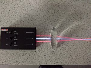
It’s worth noting that though this blog post is full of simulations to play with, there’s a lot to be said for using the ray box and getting hands-on with it all. Just remember in the real world there’s always a little reflected light from the boundary of any lens. I really like these battery powered LED ray boxes…

Once the concept of a change of speed causing a change in direction is set it’s on to the mathematics and Snell’s law allowing us to predict the shift in angle due to the change in speed. Note that the refractive index, n, is a measure of the speed of light in a substance. In vaccuo n=1 ie, the speed of light is just that. In something like diamond, which has n=2.4, the speed of light is much slower, you would have to multiply the speed by 2.4 to get the speed in vaccuo.

This simulation uses the equation above to plot the paths of the rays – be sure to move the incident ray below the normal;
and finally we get to ray diagrams for lenses.
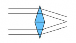
A lens is very much like a development of two prisms stacked on top of each other:

The rules of refraction are followed, resulting in the light rays converging, or diverging and the formation of images.
Again Tom Walsh’s provides us with a great Geogebra simulation;

